Abstract
In Germany, nine pioneering permeable reactive barriers (PRB) for passive in situ remediation of contaminated groundwater have been erected over the last 3-4 years (e.g., in Bernau (built 2001), Bitterfeld (1999), Denkendorf (2000), Edenkoben (1998, 2001), Karlsruhe (2000), Oberursel (2002), Reichenbach (2000), Rheine (1998) and Tübingen (1998)), all revealing interesting design and engineering features. At the Edenkoben site, one can find one of today´s probably largest funnel-and-gate (F&G) systems (appr. 450 m long, equipped with six gates). This paper provides an introduction to German PRB projects focusing on design and engineering features, as well as on some first major outcomes regarding destruction efficiency and long-term performance, where available. It is shown that F&G and related systems prevail, predominantly equipped with specially positioned or designed funnels and/or gates (e.g., relatively flat gates installed closely below ground level, or reactors receiving passively or even actively diverted/lifted groundwater). Different zero valent iron (ZVI) types or activated carbon are the exclusively applied reactive materials in German PRBs to treat chlorinated volatile organic carbons (cVOC) and polycyclic aromatic hydrocarbons (PAH), though a biological treatment zone to degrade PAHs is planned to be set up at Offenbach, and different alternative innovative materials are currently tested in a semi-technical scope at Bitterfeld and elsewhere.
As representing passive in situ groundwater remediation techniques and therefore avoiding several immanent technical drawbacks of active systems a priori, PRBs are currently regarded as promising upcoming alternatives to common active groundwater remediation technologies like pump-and-treat (Gavaskar et al., 2000, Rochmes, 2000, United States Environmental Protection Agency (U.S. EPA), 1998, 1999 and 2002, Vidic, 2001). Although installation costs are generally higher than those of other groundwater remediation technologies, operational and maintenance (O&M) costs are significantly lower, provided that the PRB will not have shown an unexpected malfunction before the year in which costs are recovered. O&M costs of PRBs are mostly attributable to monitoring measures, which are required for all remediation approaches as well. There is no permanent and massive intervention in the aquifer, and the remediation takes place in the subsurface directly inside the contaminated aquifer. Therefore, no costly installations or a specific plant have to be set up which have to be operated and maintained during a long-term run in the range of several years or even decades. In addition, the land use can resume after the installation of a PRB system, since there are few visible signs of installation above ground except for the monitoring wells.
The first PRB was set up at Borden, Ontario (Canada), in June 1991 as a pilot-scale, continuous reactive barrier (CRB) using ZVI for treatment of perchloroethene (PCE) and trichloroethene (TCE). Iron grindings collected from a local machine shop mixed with sand were deployed. The first full-scale system was installed in 1995 in Sunnyvale, California (U.S.A.) as funnel-and-gate. This system utilizes 100 % ZVI to treat TCE, dichloroethene (DCE), vinylchloride (VC) and chlorinated fluorocarbons (CFC). Since 1995, the number of U.S. pilot and full-scale PRBs has steadily increased (U.S. EPA, 2002), particularly between 1998 and 1999 (in 2002, there are about 40 PRBs in total). Predominantly, cVOCs like chlorinated ethenes (PCE, TCE) are dehalogenated via intermediates to chlorine-free degradation products (in case of PCE or TCE, e.g., via DCE and VC to halogen-free ethene as one major degradation product) using ZVI that serves as the dehalogenation reagent (mainly in the form of small filings or granules). CRBs meanwhile prove to be in favor of F&G due to economic and operational reasons. Some PRBs have been already run for more than 5 years revealing constantly high degradation rates of the pollutants, e.g., the pilot-scale F&G systems at the Moffett Federal Airfield, Mountain View, California, built during April 1996 (cVOCs are dehalogenated with ZVI), and at Dover Air Force Base, Delaware, set up in December 1997 (cVOCs are dehalogenated with ZVI as well). Recently published, comprehensive reports presented and discussed the extensive results from investigating several installations regarding key issues like long-term performance (Gavaskar et al., 2000 and 2002).
Besides chlorinated hydrocarbons (CHC) and certain radioactive elements, PRBs have been relatively rarely applied to other groundwater contaminants so far, like common heavy metals (e.g., lead, zinc, cadmium, copper), PAHs or other aromatics like benzene, toluene, ethylbenzene or xylenes (BTEX), because suitable and affordable reactive materials are still lacking or are currently only under development (Scherer et al., 2000). Activated carbon seems to be a promising reagent for the adsorptive removal of PAHs and other contaminants like highly persistent CHC, because PAHs can not be degraded on ZVI, namely as well chlorinated aromatics (Gavaskar et al., 2000, Scherer et al., 2000), due to the relatively low reduction potential of ZVI. One solution for getting rid of these components has also been demonstrated by using in situ hydrogenation catalysts like palladium. Nevertheless, these compounds are usually very expensive, toxic and may be quickly deactivated by other groundwater components or their reaction products like sulfide. Therefore, a novel, emerging trend regarding reactive materials seems to be combining different reactive and/or sorptive materials like iron and activated carbon that already perform well and are economical in PRBs where each is applied exclusively (Weiß et al., 1999, SAFIRA, 2002).
2. Current issues regarding PRB technologies
PRBs are not appropriate for all applications (Vidic, 2001). Moreover, PRB technologies have not yet gained general acceptance as established remediation technologies so far, especially across Europe, due to several reasons:
1. There is a certain lack of reliable information on long-term performance, longevity and long-term effects because of the lack of long-lasting projects in the range of decades (Puls et al., 2000, Yoon et al., 2000, Rochmes, 2000, Sarr, 2001, Vidic, 2001).
2. There is a demand for identifying all degradation pathways as well as determining precise mass balances. The considerable toxicity of intermediary or final dehalogenation products like cis-DCE, VC or ethene is also critically discussed (Wienberg, 1997).
4. Only insufficient information is currently available on the economic viability of PRBs, especially, if the performance decreases over time.
5. The knowledge of the applicability and longevity regarding combined contamination scenarios, especially for very heterogeneous and complex subsurface, is currently in a very early stage (Rochmes, 2000, Scherer et al., 2000) .
3. Development in Germany
A ddressing the issues mentioned above, the German EPA (Umweltbundesamt, UBA) already stated in late 1997 that research and development (R&D) as well as technical implementations of PRB projects had to be boosted in order to investigate their potentials and limits (Burmeier, 1997). SAFIRA (i.e., Sanierungsforschung in regional kontaminierten Aquiferen, meaning in English remedial research applied to regionally contaminated aquifers), a R&D network using specifically designed in situ reactors in a semi-technical scale for testing different reactive materials, was the first initiative to study the potentials of PRBs in a broader scope (Weiß et al., 1999). The pilot plant treats groundwater contaminated by a complex mixture of CHCs, i.e., mainly chlorobenzenes and other pollutants, at Bitterfeld, Federal State of Saxony-Anhalt . In order to promote the technical development of full-scale PRBs, the German Federal Ministry of Education and Research (BMBF) set up another PRB concerted action RUBIN (i.e., Reinigungswände und -barrieren im Netzwerkverbund, meaning in English PRB projects co-operating in a network/concerted action), consisting of several PRB projects (Birke et al., 2001 and 2002). Extensive and up to date information (in German and English) on both networks can be retrieved on the Internet (SAFIRA, 2002, RUBIN, 2002).
Below is the summary of profiles (site-specific features, key design, construction and some operational parameters, as obtainable) of current pilot- and full-scale installations of PRBs designed as F&G or CRB. In addition, a short inventory of these PRBs is provided by Table 1. Moreover, a recently emerged, interesting and innovative gate construction approach and novel sorptive materials are addressed, which are ready for application in the upcoming future.
4.1 Edenkoben, Federal State of Rhineland-Palatinate
In 1994, a massive soil and groundwater contamination by cVOCs was detected on the premises of a supplier for car manufacturers in Edenkoben, Neustadt (Weinstrasse), 40 km westward of Ludwigshafen in Southwest Germany (Rochmes, 2000, Peschla & Rochmes GmbH web site, 2002, RUBIN, 2002). The contamination was attributed to a former use of chlorinated hydrocarbon solvents for production processes. Several hot spots of contamination were found on the property, partly situated below some buildings (production facilities). A more than 400 m broad, heterogeneous cVOC plume, formed by at least three individual, partly overlapping plumes, could be identified. These individual plumes consist of different contaminants showing varying concentrations. For example, the plume in the South of the premises chiefly consists of TCE and cis-DCE (up to 8.000 m g/l cVOCs in total were found), the plume in the middle comprises 1,1,1-trichloroethane (1,1,1-TCA), TCE and cis-DCE (up to 20.000 m g/l cVOCs), whereas the plume in the North is contaminated predominantly by PCE ( » 2.000 m g/l cVOCs). The average composition of cVOCs is 20 % TCE, 50 % cis-DCE and 30 % 1,1,1-TCA.
The geology is characterized by infills and a highly heterogeneous underground (silty overlying strata, 1-6 m thick). Two relevant aquifers have to be taken into account, the lower of which is not polluted. The polluted upper aquifer is split up into 2 well permeable layers, separated by silt and silt-sand-mixtures varying in size (silty gravel-sand mixture referred to as aquifer 1a, and medium-grained sand with a small portion of fine grain referred to as aquifer 1b). There are well permeable layers with a varying thickness of 4-7 m. However, the overall permeability coefficient (kf) is poor: 1.4 × 10⁻⁴ to 4 × 10⁻⁶ m/s (av. 5 × 10⁻⁵ m/s). Grey silt and clay deposits with interstratified peat layers (thickness 1.5 m up to several meters) make up the aquifer base.
Attempts to apply soil vapor extraction as well as preliminary experiments for hydraulic treatment of the hot spots failed to meet reasonable remediation targets, therefore proving that remediation could not have been completely accomplished using only conventional approaches. Furthermore, because of the extended, relatively large plume, it was rationalized that protective measures downgradient of the hot spots became quite inevitable in order to protect neighbored properties.
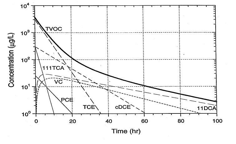
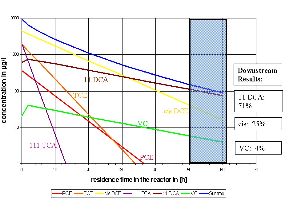
A feasibility study including column experiments employing groundwater from the site along with groundwater modeling revealed that a PRB applying ZVI and shaped as a F&G could be successfully applied for that purpose (Figure 1). Therefore, in 1998, a pilot-scale F&G for field testing for a six month operation period, was set up in the middle of the plume. As outlined in Figure 2, promising destruction rates of 99 % were observed during that term. Hence, the site owner decided to have the full-scale PRB system planned and installed, despite the fact that it would be the very first one of a predominantly privately financed full-scale PRB in Germany associated with a certain, increased risk compared to conventional techniques. Further investigations, planning and coordination work, along with all responsible authorities enabled setting up the full-scale F&G in autumn/winter 2000, which was eventually put into service in February 2001.
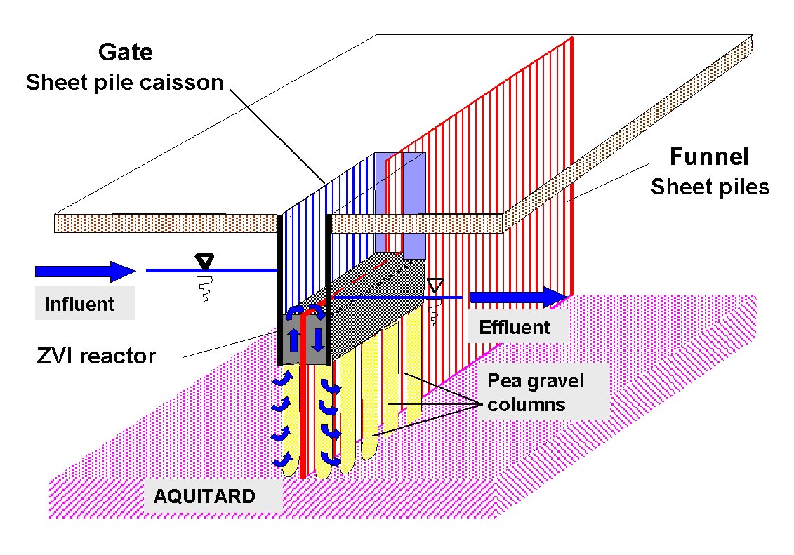
According to Figure 3, the Edenkoben gate type is designed for a diverted, vertical flow inside, i.e., the groundwater is passively lifted by a vertical drainage (gravel columns, diverting the groundwater flow by 90 ° regarding its natural, horizontal move) and thus directed through the ZVI bed that is closely installed below ground level (thus, a complete connection of the deeper, polluted groundwater areas to the gates is provided by these vertical drainages). Six gates (each 10 m long and 1.25 m wide), constructed as a sheet pile caisson (open towards its bottom) and packed with granular ZVI (825 tons in total), reached down to approximately 8 m below ground level. A continuous sheet pile wall, 400 m long and more than 14 m deep (i.e., at around 14 m depth it is pushed into the aquifer base) forms the funnel that is also running through the gates, thus separating every gate into two chambers. However, inside the gates, the sheet pile wall was buried down to 1 m below the lowest groundwater level anticipated (at 5 m below ground level), hence serving as an overflow weir between the chambers. In other words, the flow path through the ZVI is intentionally doubled, due to the particular gate design/construction (Figure 3). The sophisticated design of the PRB system in Edenkoben bases on two innovative principles:
• compared to conventional gate construction, the width of a gate, i.e., the actual (horizontal) thickness/expansion of an iron layer required for a sufficient dehalogenation is significantly reduced by shifting/diverting the groundwater flow twice vertically through a given portion of ZVI.
• By installing the gates closely below ground level, accessibility as well as potential recovery of ZVI are significantly facilitated.
According to Figure 2, the overall cVOC concentration is significantly reduced, virtually meeting remediation targets. Only 1,1,1-TCA is recalcitrant to complete dehalogenation on ZVI, because only 1,1-dichlorethane (DCA) is its major degradation product. However, this finding is in accordance with results received from column experiments earlier.
A reduced permeability of the former pilot gate was detected in 2001 during the standard monitoring program regularly performed at the site. To cope with this problem, specific in situ regeneration like applying ultrasound or other measures are currently planned/under way.
4.2 Karlsruhe, Baden-Württemberg
A full-scale F&G equipped with granular activated carbon (GAC) to treat PAHs and BTEX was erected in Karlsruhe in 2000/2001 (Schad et al., 2000, Schulze and Mußotter, 2001, Arcadis GmbH web site, 2002).
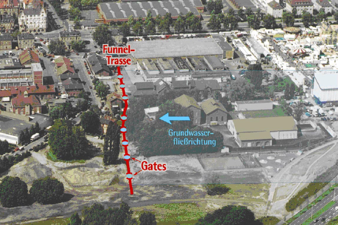
During 79 years of operations, the former gas works plant produced town gas, coke, tar, benzene and ammonium sulfate from more than 4.3 million tons of coal in total. The soil and the groundwater had been carelessly contaminated by PAHs and BTEX during that term, most likely a result of several tar oil spills scattered over the entire premises. Covering over 100,000 m2 , the premises is therefore the origin of a large PAH plume moving towards the inner city of Karlsruhe (about 200 m broad and 400 m long). In addition, a partly accompanying VC plume was encountered, however its source has not been clearly identified yet (this plume originates upgradient of the site). Maximum contamination levels detected are 500-600 m g/l of PAHs (acenaphtene is the main component), 20 m g/l of benzene and 2 m g/l of ammonium, whereas VC could be detected at up to 100 m g/l. The site is located in the Rhine valley. The aquifer is approximately 12 m thick consisting of sandy, densely bedded gravel, which is underlain by a clay layer at a depth of 16 m below ground level. The groundwater flow rate was determined at about 12 L/s under natural conditions. Since most of the PAHs are very persistent in the subsurface (i.e., it is impossible to remove them by conventional pump-and-treat approaches within a reasonable span), it was decided to focus remedial activities at this particular site on the plume rather than on the sources. Therefore, a full-scale F&G barrier charged with about 150 tons of GAC in total, for which regeneration cycles of 5-15 years are expected (depending on the concentration of the contaminants), was planned and eventually set up in January 2001. Figure 4 (top) shows an aerial picture of the site, wherein the position of the F&G is outlined, too.
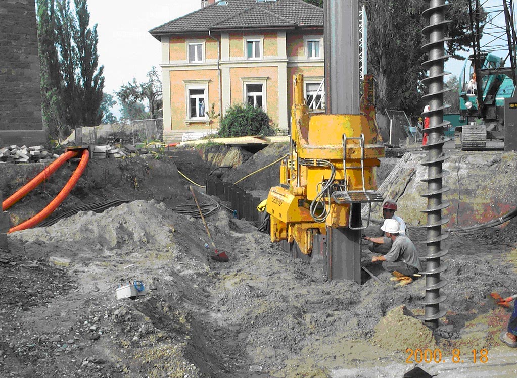
The Karlsruhe wall is about 240 m long and 17 m deep, arranged in an almost straight line, upon which eight, nearly equidistant gates are positioned (Figure 4). The funnel consists of sheet piles that were pressed, not driven, into the ground using the silent-piler-technique (Figure 5) in order to prevent damages from nearby buildings and gas supply pipelines. The gates consist of specifically perforated, cylindrical steel tubes that were brought down into the ground by means of previously set up large diameter borings (Figure 6). The elevation of a gate is schematically illustrated by Figure 4 (bottom). It can be seen that inside each cylindrical element two additional, perforated steel sheets are equidistantly incorporated on its entire length, thus separating it into three sections: two smaller spaces are generated at the perimeter inside, and a larger one in the middle to be loaded later with GAC solely. Setting up the gates commenced by driving cylindrical, large diameter (2.5 m) borehole casings (circular caisson installation) into the ground and excavating them to a final depth of 15-17 m below ground level (0.5 m below the aquifer base). At its bottom, every borehole was equipped with a 0.5 m thick layer of cast concrete serving as foundation. Prefabricated, cylindrical gate segments were connected to each other and the whole construction was lowered into each shaft/borehole (approximately 18 m in length and 1.8 m in diameter). Two inch monitoring wells were installed at the inflow and the outflow of the gates. Pea gravel, operating as filter medium and homogenizing the flow through the gates, was brought into the ground in front and behind each gate (Figure 4, bottom). By employing a clay layer, the free space left between the steel tubes and the adjacent funnel segments was sealed off against an unwanted potential bypass of groundwater. At the same time, the borehole casings were removed by hauling them up to the surface. Afterwards, the gates were closely connected to the sheet pile wall by introducing a closing sheet pile element on each side of the gate, reaching into the clay layer as well as tightly joining/connected to the sheet pile wall on its other side (Figure 4, bottom). In the next step, each gate received a protective cover equipped with a manhole in order to be able to readily control the gates during operation. Finally, the gates were charged with GAC, only using the main section in the middle.
The total costs amounted to more than 4 million €; for an operational term of 50 years the site owner expects up to 2 million € more to be spent, most probably due to exchanging GAC and monitoring. Note that The Federal State of Baden-Württemberg covered 3.5 million € of the total costs.
In early 2002, no official data regarding the performance of the Karlsruhe PRB were available, but extensive information on the ongoing monitoring is expected to be published in late 2002 or 2003.
4.3 Bernau, Federal State of Brandenburg
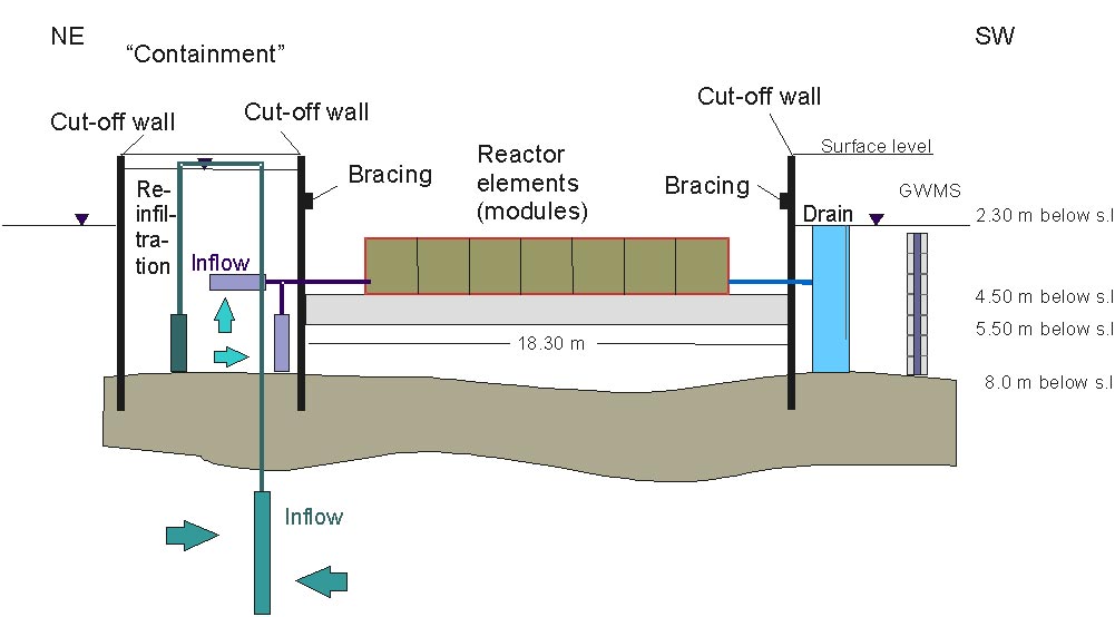
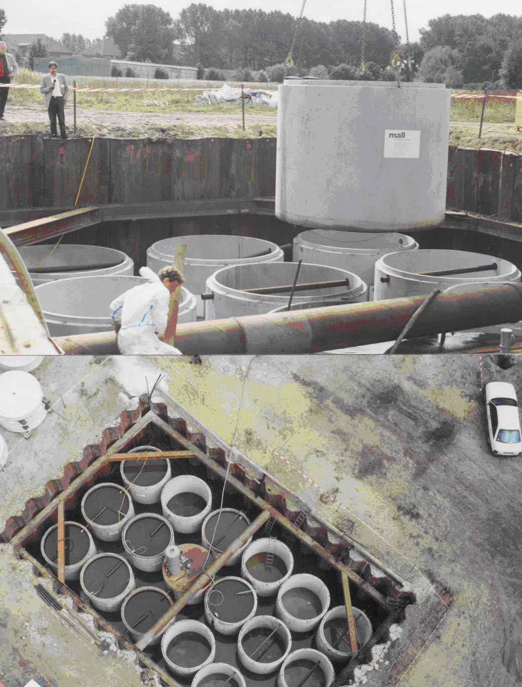
A pilot PRB was set up on the abandoned premises of a former dry cleaning facility operated by the former Soviet Union´s armed forces in the town of Bernau (northeastward of Berlin) in 2001 (Hein et al., 2002, Birke et al., 2001, RUBIN, 2002). This RUBIN project reveals several unique and unconventional construction features (Figure 7-8). For example, the gate containing 18 oversized columns (reactor elements/modules) made of reinforced concrete and loaded with ZVI or other reactive materials, is installed closely below ground level and passed quasi horizontally by lifted groundwater that actually flows through each element.
The whole system was designed to simultaneously meet two crucial, site-specific requirements that are pretty typical for a great number of sites in Eastern Germany, i.e., a very high groundwater contamination by cVOCs is encountered, which in addition affects even two aquifers lying on top of each other at the same location. The reactor elements (each with a diameter of 2.80 m, being 2.50 m high and having a total weight of 14 tons) are vertically arranged side by side in a large-scale, open outer cell near below ground level. This cell resembles a cofferdam (similar to a reinforced foundation trench, rectangular shape, 19 x 11 m, around 5 m deep, bottom cast with 1 m thick concrete), where sheet piles are intentionally left in place in order to brace the structure. Note that the system does not operate passively overall, because the groundwater is actively captured and furthermore lifted by pumping before entering the gate. However, after having entered the gate, the groundwater passes the closed, slightly over-pressurized reactor elements passively according to the artificially set up gradient (Figure 7).
Upgradient, the reactor cell is directly connected to a vertical slurry wall that entirely encompasses the center of the TCE plume associated with the first aquifer (along a length of 90 m). In other words, the hot spot, which represents and marks the place of one former heavy TCE spill/leakage, is entirely cut off.
The closed funnel construction is not only designed for serving as a containment for the source. Moreover, it works as a capturing/collecting zone for lifted groundwater using the pore volume of the soil inside in order to accumulate and mix the contaminated groundwater of both aquifers before entering the reactor: since the funnel covers an area of 425 m², a pore volume of about 750 m³ is available for holding lifted groundwater, provided that the water table is raised to its potential peak value at 1 m below ground level. By defining the gradient of the water flow towards the reactor system through the artificially increased water level in the collecting zone, the mass flux of the contaminants through the reactive system can be controlled in a wide range (Figure 7).
During the first months of operation in winter 2001/2002, initial results indicated a considerable abiotic decay of TCE, in accordance with column experiments conducted earlier. After exchange of one pore volume, the initial TCE concentration of 75 mg/l decreased to below detection limits behind the eighth module (i.e., after 27 hours and a total flow path length of 13 m).
A lternative in-situ treatment, which may synergistically benefit under controlled conditions from already occurring side-reactions inside the reactive system, is scheduled to be implemented in addition, e.g., enhanced natural attenuation downstream by feeding nutrients, hydrogen and/or methane into the system (Hein et al., 2002).
In early 2002, a L-shaped F&G system applying ZVI to treat cVOCs was installed in Oberursel northward of Frankfurt, Main (Arcadis GmbH web site, 2002). The funnel, constructed as a 0.6 m thick slurry wall, is about 175 m long and 4-19 m deep covering a total area of 2,400 m2 . The gate is located at the sharp angle of the L-shaped funnel and constructed as a wide circular ring formed by overlapping boreholes consisting of concrete (the ring has a diameter of 3.3 m). At its inflow and outflow, six overlapping boreholes each are cast with water-permeable concrete to enable groundwater to pass. The reactor ring is separated into three sections: at the inflow (i.e., at the perimeter), groundwater passes a bed of pea gravel first, before entering the iron zone. At the effluent, another bed of gravel has to be passed. Therefore, the ring-shaped reactor is loaded with iron in its middle only. The pea gravel zones serve as a filter medium and for homogenizing the flux through the reactor. The reactor is positioned vertically, hence being horizontally passed by inflowing groundwater. It is 13 m deep, 1.8 m broad, and its volume amounts to 69 m 3 . 310 tons of iron granules (1.0-1.6 mm diameter) were inserted. No information on the performance have been made available yet, however, some general facts are supplied on the Internet (Arcadis GmbH web site, 2002). Note that the cVOC dehalogenation was already verified using column experiments applying water from the site prior to the full-scale project.
4.5 Tübingen, Baden-Württemberg
A full-scale F&G system was installed in October 1998 at the so-called BEKA site in Tübingen deploying ZVI to treat a plume of cVOCs, in particular TCE, cis-DCE and VC. A detailed report can be found elsewhere (Klein and Schad, 2000). The performance of this PRB will be scrutinized in a member project of the network RUBIN between 2002 and 2004 (RUBIN, 2002).
The aquifer is about 7 m thick and consists of mostly silty gravel which is underlain by a clay layer at a depth of about 10 m below surface. The hydraulic conductivity of the aquifer was found to vary between 1 x 10⁻⁵ (valley border) and 1 x 10⁻³ m/s (valley center), and the hydraulic gradient amounts to about 0.17 %. In the past, efforts to clean-up the site by conventional pump-and-treat measures failed. This phenomenon is attributed to slow and permanent dissolution and diffusion of cVOCs from neighbored, low permeable zones into the aquifer, which may have accumulated the pollutants over decades. Therefore, passive remediation technologies like a F&G system were suggested in order to achieve the clean-up goals at sustainable costs. As a result of extensive preliminary investigations (including column tests using 100 % granular iron and a numerical flow modeling), a L-shaped funnel with a total length of 215 m was designed including three gates charged with ZVI, each of them 5 m wide (perpendicular to the groundwater flow direction) and between 0.6 m and 1.6 m wide with respect to the flow direction. The required amount of iron could be calculated using both the determined half-lives of the decay of the main contaminants (1.5 h for TCE, 3.5 h for cis-DCE and 5 h for VC), the upgradient cVOC concentrations and the estimated groundwater velocities. The amount of ZVI applied in each of the three gates differs, because it was adjusted to the upgradient cVOC concentrations and the estimated local groundwater velocities. The funnel consists of a slurry wall (0.6 m thick, stretching to a depth of 8-11 m). The gates were constructed in two steps. First, pea gravel filter zones were emplaced by overlapping boreholes upstream and downstream of the reactive iron zone to be installed afterwards. Second, the ZVI (filings, 275 tons in total) were emplaced right between the pea gravel filter zones using the same technique. Monitoring wells were installed in transects parallel to the groundwater flow upgradient and downgradient as well as within the iron zone. The installation of the whole system took 10 weeks only.
Since the installation of the Tübingen PRB, a monthly implemented monitoring program including analyses of PCE, TCE, cis-DCE, VC, Fe(II), dissolved oxygen, specific conductance, temperature, pH and redox potential as well as measurements of the water table has been performed at the site.
Inside the three gates, conditions revealing a high reduction potential associated with low values of dissolved oxygen and Eh are encountered as expected, as well as an increased pH, which is typically observed in iron walls. Maximum concentrations of cVOCs from the monitoring well upgradient of so-called gate 1 have been as high as 260 m g/l. Samples from downgradient wells (positioned in the pea gravel downstream the iron zone of gate 1 and further downstream) show concentration levels less than 10 m g/l, representing the regulatory limit. Results for all three gates indicate that within the iron zones cVOC concentrations decrease to below the detection limits. However, downgradient a slight increase of cVOC levels compared to the values in the iron zone is found, most likely due to desorption from the aquifer material or small leakages from regions within the slurry wall or the iron zone. Predominantly, the regulatory limits are not exceeded (Klein and Schad, 2000).
4.6 Offenbach, Hesse
On the premises of a former tar processing plant nearby the river Main in Offenbach, the soil and the groundwater are massively contaminated by BTEX and PAH (naphthalene, acenaphthene). According to Figure 9, it is planned to develop and test a specifically designed F&G for cleansing the BTEX and PAH polluted aquifer (RUBIN, 2002). The benzene level, which dominates the BTEX parameter here, amounts to up to 4,000 m g/l downgradient from the source towards the Main. Below the former impregnation works, which processed tar oil, huge residues of tar oil were identified (20-80 cm thick pure-phase). BTEX were detected up to a concentration of 110,000 m g/l, naphthalene amounts to up to 12,000 m g/l and PAHs (excluding naphthalene) up to about 800 m g/l. Also phenols are present at a level of up to 11 mg/l. It has to be emphasized that temporary backwaters of the river Main rinse out different fractions of pollutants in a spatially and temporally non-uniform manner. Therefore, a widely fluctuating hydrophobicity of the entire contaminant mix is observed resulting in differing sorption tendencies regarding the aquifer components. It is assumed that constant seepage and infiltration conditions most probably give rise to this upgradient phenomenon. The wall system and reactive materials (see Figure 9) to be applied (expected for 2003) are a F&G and microbiological degradation plus activated carbon, respectively. In the microbiological degradation step, nutrients are planned to be added (e.g., electron acceptors). Activated carbon is scheduled to be used primarily as an additional adsorbent for some PAHs that can not be readily destroyed biologically. A 120 m long funnel (sealing wall), approximately vertically arranged to the groundwater flow downgradient of the contamination source , will cut off and direct the contaminated groundwater towards the gate/reactor. According to Figure 9, the length and width of the gate located approximately in the middle of the sealing wall and closely below the ground level will be about 10 m. The gate will be constructed using standard engineering techniques (most probably cofferdam, sheet piles). Due to its position near the surface, the reactor will have to receive lifted groundwater. For this purpose, a sheet pile wall will intercept the aquifer flow in front of the reactor, and an additional gravel zone equipped with filter pipes will be positioned still in front of the sheet piles: it will be required to passively divert the flow into a vertical direction toward s the entry of the reactor. For that purpose, filter pipes on both sides of the sheet pile connected to each by a common pipe will be installed. Already i nside the filter pipes in front of the inflow, required electron donors will be added. Entering the reactor, the contaminated groundwater is ready for the microbiological degradation of the contaminants throughout the 8 m long gravel filter zone inside the reactor (appr. 1.5 days residence time), especially a microbiological BTEX degradation. In case of blocking by enhanced growth of microorganisms, back-washing devices are provided, too. Figure 9 reveals that the biological treatment zone will be followed by a filtration step using activated carbon in order to retain poorly soluble PAH molecules (usually components consisting of 4-6 membered aromatic rings), that may be recalcitrant to microbiological degradation.
4.7 Denkendorf, Baden-Württemberg (Drain-and-Gate)
At the trading estate of the small town of Denkendorf, located near Stuttgart, six different sources of cVOC contamination were detected (Figure 10). The main contaminants are TCE, PCE, cis-DCE and 1,1,1-TCA. In addition, groundwater is polluted by VC, stemming most probably from naturally occurring microbiological degradation of PCE/TCE. The overall concentrations of the pollutants were determined to be more than 200 mg/l total within the hot spots; pure-phase cVOCs are present, although the average total concentration of cVOCs in the groundwater is below 30 mg/l. A very high carbonate hardness is found in the groundwater due to abundant red and shelly limestone. Sulfate is determined at 200 mg/l.
The low hydraulic gradient of 2 % led planners to design a special full-scale system that traps and collects the contaminated groundwater passively (so-called drain-and-gate). This requirement is met by means of a 20 m long gravel drainage additionally equipped with filter pipes (Figure 10-11). The drainage directs the flow right towards the reactor that is loaded with GAC. The depth of the wall is about 6 m. The Denkendorf reactor was constructed as a shaft structure by means of deploying common civil engineering techniques. Using a bypass of the passively drained/directed groundwater flow, innovative reactive materials like palladium on zeolite (palladium loading: 0.5 % (w/w)) are tested directly at the site inside the reactor shaft. This work is conducted as part of the PRB network RUBIN (RUBIN, 2002). It is hoped that this approach can be upscaled to prove the effectiveness of this novel catalyst for technical applications, too. The novel catalyst has a molecular design (due to its zeolite backbone wherein palladium may be dispersed in three-dimensional molecular canals) that prevents sulfide from getting into contact and therefore swiftly poisoning the palladium, which is commonly observed during deploying the metal in contaminated groundwater.
4.8. Bitterfeld test site (the SAFIRA project)
The Bitterfeld region is well-known as a highly industrialized area for more than 100 years, where production of various lignite-based bulk and specialty chemicals in miscellaneous chemical plants, as well as open pit lignite mining (providing the main component for the chemical processes applied), have caused heavy contamination of soil and groundwater on a large scale, i.e., covering an area of at least 10 km2 . The SAFIRA test site in Bitterfeld was selected as a model site for demonstrating different approaches of cleanup technologies under field conditions by using an in situ pilot plant (Weiß et al., 1999, SAFIRA, 2002). Small-scale pilot tests using large-scale columns filled with different reactive materials (up to a few tons) are conducted to treat groundwater from the site contaminated with benzene, chlorobenzene (MCB), 1,2- and 1,4-dichlorobenzene, TCE, cis-DCE and trans-DCE. High levels of sulfate (up to 1,000 mg/l) and chloride (up to 1,300 mg/l) are also encountered. SAFIRA´s main target is to develop, implement and check innovative low-energy or passive water treatment technologies, especially applicable to mixed and complex contamination scenarios and being suitable for upscaling to full-scale applications in situ in another step.
The site is underlain by an upper and lower aquifer separated by a 8 m thick lignite seam. The upper aquifer extends approximately 20 m below ground level and is comprised of quaternary glacio-fluvial sand and gravel with intercalated silt. The lower aquifer is about 28-49 m deep and is comprised of tertiary sands. The water table in the area averages 6 m.
Five vertical well shafts (3 m in diameter) were drilled down to a depth of 23 m (perpendicular to the groundwater flow). The distance between the well shafts is approximately 19 m. Groundwater is collected from each shaft by means of two horizontal wells, each 10 m long and drilled at an angle of 60°. The shafts house 20 reactors (stainless steel) in total that range in length from 1-6 m, depending on the technology that is applied. Inside the reactors, which are passed from bottom to top, a permanent overpressure of 3 bars (2.96 atm) is maintained. Flow rates can be varied up to 400 L/h.
The combined cost for installation and design of the pilot system was around 6 million €. Some problems have been faced during the pilot test so far (2002). Anaerobic degradation of MCB could not be verified in the reactors. In addition, sulfate reduction was found to cause catalyst poisoning.
Based on promising preliminary results of the pilot test and laboratory experiments, several physical/chemical methods were selected to be tested in a large-scale in situ application, including a zeolite-supported palladium catalyst. Concluding its program in June 2002, SAFIRA is expected to receive additional public funding for pursuing its work over the next few years. One important lesson learned from the results obtained so far is that the complex mixture of contaminants to be encountered in Bitterfeld´s groundwater can be only treated successfully by applying a combination of several different treatment technologies.
5.1 Reichenbach, Baden-Württemberg
The first full-scale adsorptive PRB in Germany was erected at the former PCE distillation facility of a metal-processing plant (motorized lathes) in Reichenbach in 2000, where a homogeneously distributed cVOC contamination of the groundwater had been detected in the mid-nineties (Edel and Voigt, 2001, Hartwiger, 2001, RUBIN, 2002). The small town of Reichenbach is 10 km southeastward of Stuttgart (Southwest Germany), located in the valley of the small stream Fils. The pollution was attributed to spills related to the use of solvents that had occurred in the sewerage more than 20 years ago, but, interestingly, not at places where solvents had been stored or directly used. The cVOC concentration was determined at 0.5 mg/l.
The CRB had to be erected directly inside a manufacturing hall and was designed in form of non-overlapping boreholes (diameter 0.25 m each) charged with activated carbon and aligned in two rows (Figure 12). The boreholes were set up using caisson installation, which involves driving a large circular steel caisson into the ground and augering out the native material. The caisson was then backfilled with activated carbon and removed.
The whole wall is 20 m long and 7 m deep intercepting the entire plume that is around 12 m broad there. The actual effective thickness of the wall ranges from 0.22 m up to 0.32 m due to various possible flow paths (Figure 12). The staggered alignment of the boreholes enables some flow lines to pass one single borehole with activated carbon over its full diameter, i.e., meeting its center, too. However, then it is impossible for it to pass another borehole in the second row. Other flow lines can pass two boreholes in both rows, but each only closer to their perimeters. Therefore, the contact time varies between 110-160 h, owing to the various flow paths possible. These values are derived from the groundwater velocity of 0.002 m/h. Due to the highest water table determined at a depth of 4.5 m, the boreholes were only charged between a depth of 4-7 m. An especially acidified activated carbon was applied because of the high groundwater hardness at the site. Therefore, a common quality of activated carbon had been pretreated with acid in a specific manner before loading the CRB.
Below the bottom of the manufacturing hall consisting of cast concrete, meadow loam (a stiff, clayish, sandy brown silt) from 0.5-1.0 m down to about 3 m is found, located under a small layer of blocking-ups. Around a depth of 3 m a gravel layer is encountered (silty sandstone and limestone, below 3 m depth sharp-edged coarse gravel) reaching down to about 7 m. It is followed by the aquiclude, which is formed by a Stubensandstein layer (gray-green clay stone, partly destrengthened/disintegrated to silt) being pretty typical for this region in Southwest Germany. The upper aquifer, which is contaminated only, is located in the gravel layer revealing a flow direction from Northeast to Southwest (the overall permeability coefficient k f is 1×10⁻⁵ m/s), whereas the small river Fils, 300 m southward of the contaminated area, is the receiving watercourse.
It is estimated that the barrier will have to be in operation for about ten years. Compared to a conventional pump-and-treat process, the break-even-point is expected to be reached within six years after installing at the latest, not including interests. The total investment costs added up to about € 120,000, whereby the installation/engineering and activated carbon amounted to € 55,000 and € 25,000, respectively.
During two years of operation since 2000, the CRB in Reichenbach has shown a significant reduction in cVOC concentration: According to Figure 13, cVOCs upstream from the wall (only one monitoring well is placed, denoted as BK1) range from 0.11 mg/l up to 0.22 mg/l versus 0.03-0.04 mg/l in monitoring well BK2 and 0.008-0.02 mg/l in BK3 downstream, for the term of October 2000 until January 2002. Therefore, a consistently good reduction has been verified so far, though higher cVOC values measured at BK5 (inside the wall, located at one of its edges) might indicate a problem. However, note that a standard remediation goal for cVOCs in Germany would be not higher than 0.01 mg/l.
It is planned to add some more monitoring wells to the five existing ones in order to get more information on the spatial performance.
In 1998, a pilot-scale CRB containing two types of ZVI in two separated segments (total length: 22.5 m) was installed approximately 400 m downstream a former dry-cleaning facility located in the small town of Rheine, about 30 km westward of Osnabrück (Mull und Partner GmbH web site, 2002, RUBIN, 2002). Investigating the site is an important part of the mission of the RUBIN network: the PRB is extensively used for monitoring including coring both ZVI types and groundwater modelling in order to determine performance and predict long-term effect (Ebert et al., 2001).
The source is directly located at the mentioned former dry-cleaning facility which was rebuilt in the eighties to residential buildings (row houses) and where pump-and-treat is permanently in operation, i.e., in the small garden area located behind the houses. PCE and cis-DCE are the primary contaminants of concern at the site. Initial maximum concentrations in the plume were 20,000 µg/l for PCE and 500 µg/l for cis-DCE. Leakages and spills have resulted in a relatively large plume that is about 500 m long and 250 m wide. So far, it has drifted towards the river Ems which flows about 100 m ahead (westward) the head of the plume. Currently, the monitoring of the plume indicates that the plume is currently tending toward changing its direction than moving straight ahead toward the river.
The aquifer consisting of loamy sand extends between 5-10 m below ground level. The water table is about 3 m below ground level. The hydraulic conductivity varies between about 0.1 and 0.9 m/d.
The Rheine pilot CRB is 22.5 m long, 0.6-0.9 m thick and about 6 m deep. According to Figure 14-15, a single row of overlapping boreholes (diameter 0.9 m) was constructed by utilizing caisson installation (driving a suitable circular steel caisson into the ground and augering out the native material), which were filled with ZVI and clean soil up to groundwater level and ground level, respectively. Two types of ZVI were employed: on the right side (from upstream), the boreholes contain 69 tons of granular iron mixed with gravel at a 1:2 volume ratio (34.5 tons each of iron and gravel) over a length of 10 m. 85 tons of iron sponge were applied on the left side (12.5 m long). A concrete-filled borehole separates the two segments. The so-called iron sponge is stemming from its obvious appearance: the small, dark grey or virtually black pellets (average diameter about 1 cm) resemble a pumice-like material, to some extent. It consists of wood shavings or wood chips impregnated with hydrated and partly reduced iron oxide. It is commonly used for removing hydrogen sulfide in oil and gas processing operations and was supplied by a steelworks located in Hamburg, Germany.
Design costs were at 32,000 €. Installation costs including construction and reactive material amounted around 95,000 €. An additional amount of 14,000 € was spent on monitoring and 25,000 € on the installation of gas measurement devices.
The Rheine wall was the first CRB to be erected in Germany. It was set up during a R&D project as a pilot PRB in the middle of the relatively broad cVOC plume in order to study the degradation of cVOCs in a field scale and to gain as much possible fundamental data on the feasibility and long-term performance in general. Therefore, no specific target cleanup concentrations were defined before its implementation, although a value fully accepted by the involved authorities was 10 µg/l. However, the PRB has temporarily resulted in significant reduction in the concentration of PCE (Figure 16). The effluent concentration of PCE leaving the granular iron section of the wall was temporarily determined to be 33 µg/l (compared to 17,000 µg/l in the influent) and 400 µg/l for the iron sponge (compared to 14,500 µg/l in the influent). These values are valid for a short section covering the first few meters behind the wall only. Several meters downstream, higher concentrations are encountered again. Only small amounts of metabolites like DCE have been detected behind the barrier so far. No VC was observed at all, neither in the influent nor effluent of the PRB. Considerable hydrogen evolution was detected shortly after installing the PRB only, in accordance with column experiments performed prior to installing the wall and associated with a complete reduction of nitrogen to ammonia. Due to an increasing microbial activity at the site since 1998, the hydrogen emission has been decreasing significantly and virtually vanished in 2001. It was found that reduction of nitrate has meanwhile switched to yield nitrogen or dinitrogen oxide presumably. The sulfate effluent concentration is decreasing, most probably due to its reduction to sulfides.
The concentration of dissolved iron and manganese in the reactive barrier and the effluent was found to be pretty low, i.e., between 0.3-0.1 mg/l, which is below the influent concentrations.
A significant decrease in the degradation efficiency of the in situ reactor have been detected regarding the granular iron section: the degradation rate dropped to around 90 % only (Figure 16, bottom), whereas the iron sponge reveals a constant rate of 99 % over the whole term since 1998. Funded by the ongoing R&D PRB network RUBIN, more R&D work is currently being performed and still to come to investigate whether potential precipitation of various mineral phases within the reaction zone affects the degradation efficiency, and which differences in composition of the reactive materials may cause the effects observed (Ebert et al., 2001). Therefore, the barrier is cored several times for scrutinizing the surface properties of the ZVI types applied. An accompanying characterization of microorganisms that are assumed to have already settled is also planned. More geologic and hydrogeologic data have to be gathered in order to clarify the spatially and temporally very heterogeneous and apparently instationary distribution of the contaminants in the plume, which has changed its shape over time, most probably partly due to the active remediation conducted at the source. A recent campaign probing the cretaceous aquitard has surprisingly revealed a considerable PCE contamination and a certain porosity therein, which had been unknown before. It is therefore assumed that the barrier might be underflowed by contaminated groundwater to a certain extent, hence resulting in the currently observed, feigned poor degradation rates of the granular iron section of the Rheine wall.
6. Innovative engineering approach for gate construction (URS Corporation)
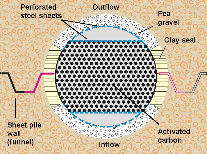
URS Corporation Germany (former Woodward Clyde International (WCI) Umwelttechnik) has developed a special approach for the easy recovery of different types of reactive media from a reactor without harming or even demolishing the construction (Beitinger, 1998). The patented system includes filtration layers to prevent fine soil particles from intruding the reactor. Potential precipitation of iron and manganese oxides can be avoided as well. Figure 17-18 reveal the main design components. Interior wall elements, made of specially designed brick elements or precast concrete formwork, are designed to load with the reactive medium. A filter layer, consisting of gravel or sand, is established between the trenched aquifer and the interior wall elements. They are perforated (in order to let the groundwater pass the reactor) and equipped with horizontally arranged, stabilizing elements serving as a protective measure against the earth pressure. Furthermore, a clay seal withholds both rain water from entering the system and the reactive material from getting into contact with atmospheric oxygen. A cover plate can be removed for recovering and replacing the reactive medium, if required. It can be readily made in waterproof and airtight quality.
The installation process is performed stepwise and described in the following. In the first step, the foundation trench required for inserting the reactor elements is made. Therefore, sheet piles are driven into the ground in 2 equidistantly aligned rows first (i.e., down up to 2 m into the aquifer base). According to the desired width of the designed reactor, the distance between the sheet piles has to be adjusted to 1 m or more. Once having completed this cofferdam-like installation, the soil between the sheet piles is excavated. An open ditch is used to pump off intruding groundwater, keeping its level permanently below excavation level. After having completed excavation, a concrete base layer is cast in situ at the bottom of the foundation trench. Draining is maintained throughout all these operational steps. Additional crossbeams may be installed in order to support the horizontal earth pressure. At this stage, the preformed formwork elements and the filter gravel are inserted and placed, embarking with the first element directly on the concrete layer at the bottom. During the advancing work on the construction upwards toward ground level, it is reasonable to let the groundwater subsequently rise again, i.e., eventually to its natural level. After that, the sheet piles can be removed, and the construction is ready to take up the reactive material (ZVI or GAC and so forth). Finally, a clay sealing and a cap can be emplaced to complete the construction. In addition, bank protection (if the PRB is located near a shore, as given in the sketches), monitoring wells and a roadway may be provided: the roadway may facilitate access to the PRB during maintenance, e.g., for taking away replaced reactive material from the PRB in the future, if required. Figure 17 and 18 show an approximately 30 m long gate in its longitudinal elevation. The construction costs for a PRB being 8 m deep are estimated to range from 450-750 € per m2 , excluding the reactive medium. For a 0.3 m thick layer of activated carbon, a further amount of 160 €/m2 had to be added.
7. Innovative sorptive materials: Dr. Ecker´s sorbents (Dr. Ecker GmbH)
The so-called Absorptionsmittel 3 and Absorbfloc are comprised of clay- like minerals, which are able to exchange divalent heavy metal ions like those of copper, nickel, zinc, cadmium and lead, for harmless alkaline earth metals (Dr. Ecker GmbH web site, 2002). Trivalent ions like those of chromium are readily exchanged by trivalent aluminum or iron. The exchange is not based on physical adsorption. Because chemical reactions are involved, the absorptive material exhibits a high capacity and efficiency for removing heavy metals, thus making it possible to attain very low heavy metal concentrations in contaminated water. The high affinity of heavy metals for these innovative and cheap absorbents even enables removal of heavy metals from aqueous solutions containing complexing agents. Furthermore, Dr. Ecker´s absorbents can remove other toxic compounds, (e.g., arsenic compounds form insoluble components together with iron or aluminium ions). Removing hexavalent chromium can be performed by applying the absorbent in combination with a suitable reducing agent. Because of its entire inorganic composition as well as its striking chemical and physical stability, the materials can be easily utilized in PRBs. Already widely and successfully used for process water clean-up, e.g., at metal plating works, it is intended to extensively test the absorbents in a PRB designed for heavy metal removal soon. Processes deploying these absorbents benefit from the very strong and stable fixation of heavy metals always occurring. Moreover, the material´s particle size can be readily adapted to prevailing hydraulic conditions at a particular site.
In Germany, PRBs have been recognized as potentially attractive alternatives to common groundwater remediation techniques. Public funding for numerous projects (R&D, pilot- and full-scale installations) amounts to about 15 million € in total, hence demonstrating the willingness to support development of PRBs. Depending on their overall performances that have to meet German clean-up goal standards, especially on the long-term run, PRBs have the potential to gain broad acceptance that is still lacking. Regarding several sites, extensive performance data are expected within the next years, therefore providing a good base for understanding and assessing benefits and limits of this technology thoroughly.
F unding for this study being part of the author´s member project with RUBIN was provided by the BMBF. Special thanks to Dipl.-Geol. Michael Rochmes and Dipl.-Ing. Theo Woll (Peschla & Rochmes GmbH, Kaiserslautern, for Edenkoben), Dipl.-Geol. Peter Hein (INGAAS GmbH, Berlin) and Dipl.-Ing. L. Vigelahn (Technical University of Berlin) and Dipl.-Geol. Martina Freygang (BBG GmbH, Waldstadt), all for Bernau, Dipl.-Ing. Peter Hartwiger (Stuttgart, for Reichenbach), Dipl.-Geograph Markus Schleyer (Stadtwerke Karlsruhe GmbH) and Dipl.-Ing. Kerstin Schmidt (ARCADIS Trischler u. Partner GmbH, Karlsruhe), both for Karlsruhe, Dr.-Ing. Wilfried Möller and Dr. Martin Wegner (Mull und Partner GmbH, Hannover, for Rheine), Dr. Hermann Schad (I.M.E.S. GmbH) and Dr. Christoph Schüth (University of Tübingen), both for Denkendorf, Dipl.-Ing. Eberhard Beitinger (URS Corporation, Dreieich), who all provided valuable information, data and images.
`Arcadis GmbH` web site. <http://www.arcadis.de> (May 1st, 2002).
Beitinger, E. (1998). Permeable Treatment Walls Design, Construction, and Cost. NATO/CCMS Pilot Study 1998 Special Session Treatment Walls and Permeable Reactive Barriers Number 229, Feb. 22-28, 1998, Vienna , EPA 542-R-98-003, 6-16.
Birke, V., Burmeier, H., and Rosenau, D. (2001). New large scale PRB network RUBIN launched in Germany. 2001 International Containment & Remediation Technology Conference and Exhibition , Orlando, Florida, < http://www.containment.fsu.edu/cd/content/ > (May 1 st , 2002).
Birke, V., Burmeier, H., and Rosenau, D. (2002). PRB Technologies in Germany: Recent Progress and New Developments. In: Rem. Chlorinated Recalcitrant Compd., Int. Conf., 3rd. Battelle Press: Columbus, Ohio, in press.
Burmeier, H. (1997). Die Bedeutung des Innovationspotentials von durchströmten Reinigungswänden für die Sanierung von Altlastenstandorten in Deutschland. Sanierung von Altlasten mittels durchströmter Reinigungswände, Vorträge und Diskussionsbeiträge des Fachgespäches am 27.10.1997 im Umweltbundesamt in Berlin , Umweltbundesamt, ed., Berlin, Germany, 6-21.
Ebert, M., Schäfer, D., and Köber, R. (2001). The use of column experiments to predict performance and long term stability of iron treatment walls. Proceedings: 2001 International Containment & Remediation Technology Conference and Exhibition , Orlando, Florida.
´Dr. Ecker GmbH´ web site. < http://www.dr-ecker-gmbh.de > (May 1, 2002).
Edel, H.-G.; Voigt, Th. (2001). Aktive und passive Grundwassersanierung ein Verfahrens- und Kostenvergleich. Terratech. Mainz, Germany, 1/2001, 40-44.
Gavaskar, A., Gupta, N., Sass, B., Janosy, R., and Hicks, J. (2000). Final design guidance for application of permeable reac tive barriers for groundwater remediation. Battelle Press, Columbus, Ohio.
Gavaskar, A., Sass, B., Gupta, N., Drescher, E., Yoon, W.-S., Sminchak, J., Hicks, J., and Condit, W. (2002). Final report evaluating the longevity and hydraulic performance of permeable reactive barriers at Department of Defense sites. Battelle Press, Columbus, Ohio.
Hartwiger, P. (2001). Full-scale-Anlage mit Aktivkohle am Standort Reichenbach. Paper presented at the ITVA-Fachtagung `Reinigungswände auf dem Vormarsch .` (Proc. Workshop on PRBs) , Oct. 24 th , 2001, Magdeburg, Germany.
Hein, P., Vigelahn, L., and Freygang, M. (2002). Personal communication , INGAAS GmbH, Techical University of Berlin, Berlin, and BBG GmbH, Waldstadt, Germany.
Klein, R., and Schad, H. (2000). Results from a full scale funnel-and-gate system at the BEKA site in Tübingen (Germany) using zero-valent iron. Contaminated Soil 2000 (Proceedings of the Seventh International FZK/TNO Conference on Contaminated Soil 18-22 September 2000) , Leipzig, Germany, 917-923.
´Mull und Partner GmbH´ web site. < http://www.mullundpartner.de > (May 1st, 2002).
´Peschla & Rochmes GmbH´ web site. < http://www.gpr.de > (May 1st, 2002).
Rochmes, M. (2000). Erste Erfahrungen mit Reaktiven Wänden und Adsorberwänden in Deutschland. Boden und Altlasten Symposium 2000 , Franzius, V., Lühr, H.-P., and Bachmann, G., eds., Berlin, 225-245.
RUBIN < http://www.rubin-online.de > (May 1st, 2002) .
SAFIRA. < http://safira.ufz.de > and < www.rtdf.org/public/permbarr/prbsumms/profile.cfm?mid=76> (May 1st, 2002).
Sarr, D. (2001). Zero-Valent-Iron Permeable Reactive Barriers How Long will they Last? Remediation , Spring 2001, John Wiley & Sons, Inc., 2001, 1-18.
Schad, H., Haist-Gulde, B., Klein, R., Maier, D., Maier, M., and Schulze, B. (2000). Funnel-and-gate at the former manufactured gas plant site in Karlsruhe: sorption test results, hydraulic and technical design, construction. Contaminated Soil 2000 (Proceedings of the Seventh International FZK/TNO Conference on Contaminated Soil 18-22 September 2000) , Leipzig, Germany, 951-959.
Scherer, M. M. S., Richter, S., Valentine, R. L., and Alvarez, P. J. J. (2000). Chemistry and microbiology of reactive barriers for in situ groundwater cleanup. Crit. Rev. Environ. Sci. Technol. , 30(3), 363-411.
Schulze, B., and Mußotter, T. (2001). Sanierung des ehemaligen Gaswerksgeländes Karlsruhe-Ost mit funnel-and-gate (Aktivkohle). Altlasten 2001 Neue Verfahren zur Sicherung und Sanierung. Burkhardt, G., Egloffstein, T., and Czurda, K., eds., ISBN 3-9806840-3-2, Karlsruhe, Germany, 47-58.
United States Environmental Protection Agency (1998). Permeable reactive barrier technologies for contaminant remediation. EPA/600/R-98/125 , Washington DC.
United States Environmental Protection Agency (1999). Field applications of in situ remediation technologies: permeable reactive barriers. EPA-542-R-99-002 , Washington DC.
United States Environmental Protection Agency (2002). Field applications of in situ remediation technologies: permeable reactive barriers. Washington, DC.
Vidic, R. D. (2001). Permeable reactive barriers: case study review. GWRTAC E-Series Technology Evaluation Report TE-01-01 , Ground-Water Remediation Technologies Analysis Center, Pittsburgh, PA.
| TABLE 1. Overview of Permeable Reactive Barrier Installations in Germany (March 2002). | ||||||
Startup |
Site |
Contaminants |
Status |
Construction |
Reactor |
Total Costs [€] |
May 98 |
Edenkoben, industrial plant, supplier for car manufacturers |
cVOCs (cis-DCE, 1,1,1-TCA, TCE, PCE) |
Pilot-scale |
F&G, length 30 m, depth appr. 15 m, 1 gate |
Granular ZVI, 2 chambers, vertical flow (up and down) |
350,000 |
| Feb. 01 | Full-scale | F&G, length 440 m, depth 15 m, 6 gates | 1,750,000 | |||
June 98 |
Rheine, former dry cleaner´s |
cVOCs (PCE, TCE, cis-DCE) |
Pilot-scale |
CRB, overlapping boreholes (diameter 0.9 m) in 1 row, length 22.5 m, depth 6 m |
2 iron types: Granular ZVI and iron sponge in separated sections |
170,000 |
Oct. 98 |
Tübingen, former industrial site |
cVOCs (TCE, cis-DCE, MCE) |
Full-scale |
F&G, length 200 m, depth 10 m, 3 gates |
ZVI, boreholes, horizontal flow |
600,000 |
Oct. 99 |
Bitterfeld, chemical industry |
Chlorobenzenes, CHC, phenols |
Pilot-scale, R&D only |
5 shafts equipped with steel reactors, depth 24 m |
GAC, ZVI, ORC, nutrients etc |
600,000 |
Jan. 00 |
Reichenbach an der Fils, metal-processing industry |
cVOCs (PCE, TCE, cis-DCE) |
Full-scale |
CRB, non-overlapping boreholes in 2 rows, length 20 m, depth 7 m |
Activated carbon, specially conditioned |
200,000 |
Jan. 01 |
Karlsruhe, former gas works plant |
PAHs, VC |
Full-scale |
F&G, length 240 m, depth appr. 17 m, 8 gates |
GAC |
4,000,000 |
Aug. 01 |
Denkendorf, trading estate |
cVOCs (PCE, TCE, TCA, cis-DCE, VC) |
Full-scale |
Drain-and-gate, 1 gate (shaft, depth 6m), drai-nage: length appr. 90 m |
Activated carbon |
600,000 |
Sep. 01 |
Bernau, former dry cleaner´s (abandoned military site) |
cVOCs (TCE), very high concentrations in 2 aquifers |
Pilot-Scale, mainly R&D for potential scale-up |
Special F&G design capturing 2 contaminated aquifers, closed funnel, partly operated actively |
Granular ZVI, microbiology and/or palladium planned |
1,500,000 |
Sep. 02 |
Denkendorf, trading estate |
mainly VC is targeted |
Small pilot-scale, treatability/feasibility |
Columns installed inside the shaft using a bypass |
Pd on zeolites, hydrogen |
120,000 |
Jan. 02 |
Oberursel, industry |
cVOCs |
Full-scale |
F&G, length 175 m, depth 4-17 m, 1 gate |
Granular ZVI |
Not available |
Figures
|
Fig. 1. Edenkoben: Degradation of VOCs according to column experiments. All images pertaining to Edenkoben courtesy of Peschla & Rochmes GmbH, Kaiserslautern, Dipl.-Geol. Rochmes, Dipl.-Ing. Woll. |
|
Fig. 2. Edenkoben: Validation of cVOC degradation 6 months after installing the pilot gate. |
|
Fig. 3. Cross-section of an Edenkoben gate designed for vertically diverted flow. |
|
Fig. 4. Overview of the full-scale F&G PRB (top) and the detailed gate construction (bottom) in Karlsruhe applying activated carbon to treat PAHs, BTEX and VC at the former gas works (all images regarding Karlsruhe provided by Stadtwerke Karlsruhe GmbH, Dipl.-Geogr. Markus Schleyer, Arcadis Trischler & Partner GmbH, Karlsruhe, Dr. Schulze, Dipl.-Ing. Schmidt) . Funnel-Trasse = funnel routing (course), Grundwasserfließrichtung = GW flow direction. |
|
|
|
Fig. 5. Sheet piling for setting up the funnel at the PRB in Karlsruhe deploying the silent piler technique that particularly enables sheet piling in housing areas where limited space is available only . This procedure does not cause heavy noise at all. |
|
Fig. 6. Setting up the gates at the Karlsruhe barrier . |
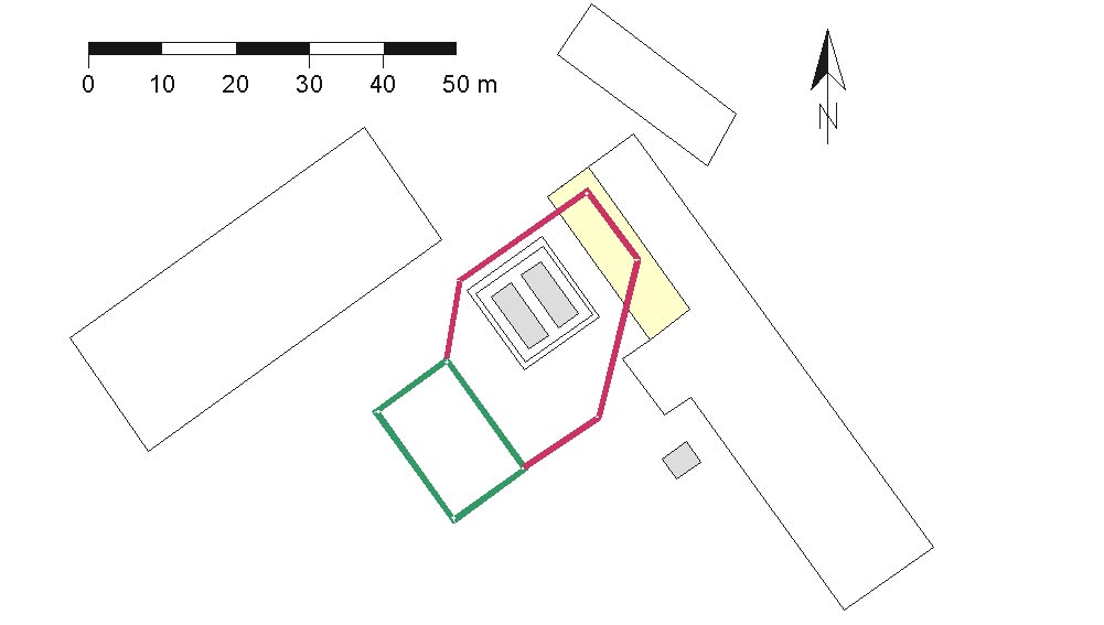
|
Fig. 7. Top: top view of the Bernau F&G system (closed funnel = containment zone, for collecting and mixing lifted groundwater of both aquifers, constructed as a slurry wall = hexagon, gate = rectangle attached to the hexagon), it surrounds the former TCE tanks now being used for storing lifted GW; bottom: elevation of the gate system = reactor; courtesy of BBG mbH, Waldstadt, Dipl.-Geol. Freygang, INGAAS GmbH, Berlin, Dipl.-Ing. Hein, Technical University of Berlin, Dipl.-Ing. Vigelahn. |
|
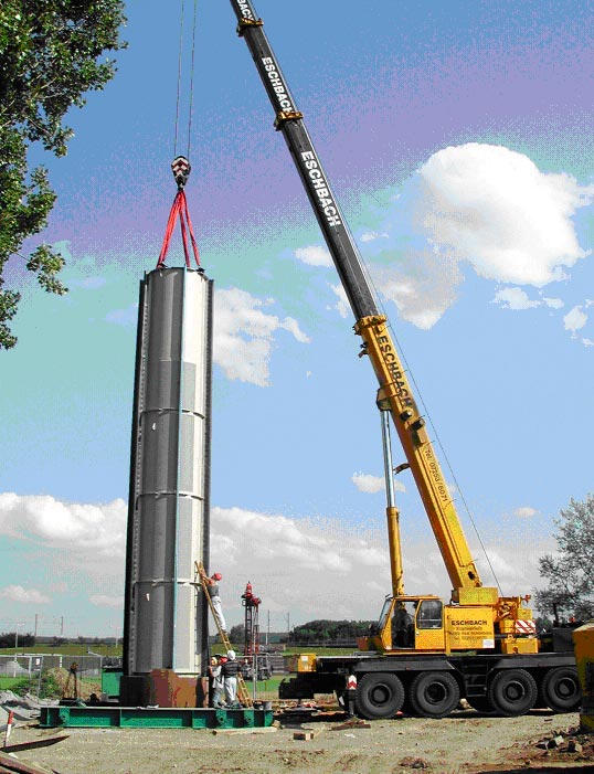
|
|
Fig. 8. Fitting/installation of the single reactor modules (top) and overview of the gate construction of the Bernau PRB (bottom, September 2001). Modules were partly filled with ZVI only and not equipped yet with cover plates (single plates can be seen at the left margin (top) of the bottom photo) |